TM-5-3805-264-13-P - Page 26 of 660
TABLE OF CONTENTS - Continued
Page No.
WP Sequence No.
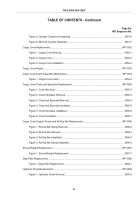
Figure 2. Hydraulic Pump Installation.
.........................................................................................
0059-5
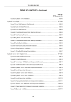
Hydraulic Pump Repair.
.....................................................................................................................
WP 0060
Figure 1. Drive Shaft Retaining Ring Removal.
...........................................................................
0060-2
Figure 2. Pump Hardware Removal.
...........................................................................................
0060-2
Figure 3. Drive Shaft Removal.
....................................................................................................
0060-3
Figure 4. Check Assemblies and Roller Bearings Removal.
.......................................................
0060-3
Figure 5. Gear Housing Removal.
...............................................................................................
0060-4
Figure 6. Hydraulic Pump Disassembly.
......................................................................................
0060-4
Figure 7. Check Assemblies and Roller Bearings Installation.
....................................................
0060-5
Figure 8. Pocket Seal Installation.
...............................................................................................
0060-6
Figure 9. Gear Housing and Drive Shaft Installation.
..................................................................
0060-6
Figure 10. Pump Hardware Installation.
......................................................................................
0060-7
Figure 11. Drive Shaft Retaining Ring Installation.
......................................................................
0060-7
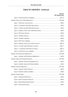
Hydraulic Control Lever Replacement.
..............................................................................................
WP 0061
Figure 1. Rear Access Panel Removal.
.......................................................................................
0061-2
Figure 2. Connector Removal.
.....................................................................................................
0061-3
Figure 3. Transmission Shift Cable and Components Removal.
.................................................
0061-4
Figure 4. Transfer Case Shift Cable and Components Removal.
................................................
0061-5
Figure 5. Hydraulic Control Cable and Components Removal.
...................................................
0061-6
Figure 6. Handle Assemblies Removal.
.......................................................................................
0061-7
Figure 7. Hydraulic Control Lever Removal.
................................................................................
0061-8
Figure 8. Hydraulic Control Lever Installation.
.............................................................................
0061-9
Figure 9. Handle Assemblies Installation.
..................................................................................
0061-10
Figure 10. Hydraulic Control Cable and Components Installation.
............................................
0061-11
Figure 11. Transfer Case Shift Cable and Components Installation.
.........................................
0061-12
Figure 12. Transmission Shift Cable and Components Installation.
..........................................
0061-13
Figure 13. Connector Installation.
..............................................................................................
0061-14
TM 5-3805-264-13&P
xii
Back to Top


