TM-5-3805-264-13-P - Page 21 of 660
TABLE OF CONTENTS - Continued
Page No.
WP Sequence No.
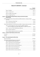
Figure 7. MCS Control Box Cover Assembly.
..............................................................................
0023-5
Figure 8. MCS Remote Control Plug Assembly.
..........................................................................
0023-6
Material Control System (MCS) Control Unit Maintenance
(M917A1 with MCS and M917A2 with MCS).
............................................................................
WP 0024
Figure 1. MCS Control Unit Removal.
.........................................................................................
0024-2
Figure 2. MCS Control Unit.
.........................................................................................................
0024-3
Figure 3. MCS Control Unit Installation.
......................................................................................
0024-4
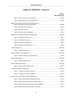
Material Control System (MCS) Switch Replacement.
.......................................................................
WP 0025
Figure 1. MCS Rear Panel Removal.
..........................................................................................
0025-1
Figure 2. MCS Switch Removal.
..................................................................................................
0025-2
Figure 3. MCS Switch Installation.
...............................................................................................
0025-3
Figure 4. MCS Rear Panel Installation.
.......................................................................................
0025-4
Taillight Replacement.
........................................................................................................................
WP 0026
Figure 1. Taillight Replacement.
..................................................................................................
0026-2
Marker Clearance Light Replacement.
...............................................................................................
WP 0027
Figure 1. Marker Clearance Light Replacement.
.........................................................................
0027-2
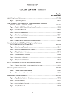
Reflector Replacement.
......................................................................................................................
WP 0028
Figure 1. Reflector Replacement.
................................................................................................
0028-1
Body Up Switch Replacement.
...........................................................................................................
WP 0029
Figure 1. Body Up Switch Replacement.
.....................................................................................
0029-2
Transport Lock Switch Replacement.
................................................................................................
WP 0030
Figure 1. Transport Lock Switch Removal.
..................................................................................
0030-2
Figure 2. Transport Lock Switch Installation.
...............................................................................
0030-3
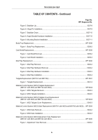
Beacon Warning Light Wiring Harness Maintenance.
........................................................................
WP 0031
Figure 1. Beacon Warning Light Hardware Removal.
.................................................................
0031-2
Figure 2. Beacon Warning Light Wiring Harness Removal.
........................................................
0031-3
Figure 3. Beacon Warning Light Wiring Harness Installation.
.....................................................
0031-4
Figure 4. Beacon Warning Light Hardware Installation.
..............................................................
0031-5
TM 5-3805-264-13&P
vii
Back to Top

