TM-5-3895-371-10 - Page 28 of 103
TM 5-3895-371-10
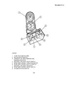
(7) Material Low Level Indicator - With the Material Low Level switch ON, and material in the tank gets low, the
indicator comes ON to warn the operator
(8) Spray Bar Control On/Off Switch - Activates the air cylinder which controls the opening and closing of the spray
bar nozzles
(9) Bitumeter Wheel UP/DN Switch - Activates the air cylinder which raises and lowers the bltumeter wheel
(10) Hydraulic Control Knob - Controls the speed of the hydraulic pump which develops the pressure of the
hydraulic fluid to the hydraulic motor
(11) Fine Control Knob - After the hydraulic control knob is set to the required pump speed setting, the fine control
knob is adjusted up against the control knob to maintain accurate setting
(12) Lock Ring - The lock ring is adjusted against the fine control knob to lock in desired position
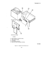
(13) Cab Override Control - This control, when pulled up, releases the hydraulic pump and removes pressure from
the system
(14) Rear Platform Override Control - Provides control from rear of distributor to release system hydraulic pressure
b. Hydraulic Reservoir and Filter
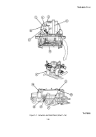
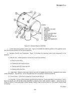
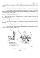
The hydraulic reservoir and filter (fig. 2-2) contains the hydraulic fluid and filtration for the
hydraulic system
(1) Fill Cap - Provides opening to fill hydraulic reservoir tank
(2) Temperature Gage - Provides visual indication of temperature of hydraulic fluid.
Reads 0-500. Normal reading
is below 185
°
F.
(3) Breather - Provides vent for tank.
(4) Filter - Contains filter element that strains any foreign matter out of hydraulic fluid.
(5) Filter Vacuum Gage - Indicates when filter element requires replacing.
Element must be replaced when gage
indicates 17 in. Hg maximum
(6) Drain Plugs - Two drain plugs, one at each end of tank, used to drain hydraulic fluid when changing filter
element or maintenance is performed
(7) Temperature Switch - The temperature switch closes when the hydraulic fluid reaches 185°F and provides a
visual indicator to the operator in the cab.
(8) Sight Gage - Provides a visual indication of the hydraulic fluid level in the tank
(9) Hydraulic Reservoir Tank - The hydraulic reservoir tank contains 20 gal of hydraulic fluid used to operate the
hydraulic pump and motor.
2-4
Back to Top

