TM-5-3895-371-10 - Page 29 of 103
TM 5-3895-371-10
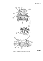
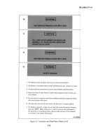
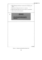
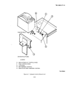
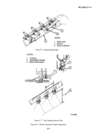
Figure 2-2. Hydraulic Reservoir and Filter
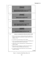
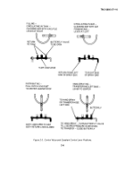
c. Control Valve and Quadrant Control Lever.
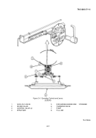
Figure 2-3 illustrates the different positions of the quadrant control
lever and the valve positions for the various operations
d
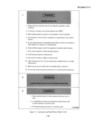
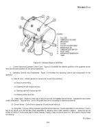
Operating Controls and Components.
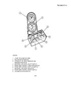
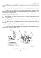
Figure 2-4 illustrates the operating controls and components for the
distributor
(1) Vacu-flo Lever - Allows operator to set vacu-flo to one of four positions
(a) Vacuum off for filling.
(b) Cleaning left half of spray bar only
(c) Cleaning right half of spray bar only
(d) Cleaning entire spray bar
(2) Intake Valve - Bolted to under side of tank at rear end, immediately below the tank.
Operated by lever below
control valve levers. Two positions: one for filling tank and one for circulating or distributing material.
(3) Control Valves - Control flow to spray bar (4) and transfer valve (6).
(4) Spray Bar - Turn-up, folding extension type End sections tapered.
Quickly adjustable in increments of 1 and 2
feet to any length up to 24 feet Bar height adjustable by adjusting stops under operator’s platform.
Spray bar can be
shifted 14 inches (7 inches each side of center) laterally, making it easy to follow a given line.
End section may be folded
for traveling.
TA 075434
2-5
Back to Top

