TM-5-3895-371-24-P - Page 155 of 330
TM 5-3895-371-24 & P
(1)
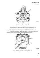
Place the pump in a shaft down position. Remove six capscrews (1) and lockwashers
(2). Lift off pump cover (3).
(2)
Remove plate (4), shim gasket(s) (14) and O-ring (5).
(3)
Remove spacer assembly (7, fig. 3-5) which includes the spacer and a dowel pin. Do
not remove the dowel pin from the spacer assembly unless damaged. Note the relationship of the valve
plate (10, fig. 3-7), plate (4, fig. 3-5), and spacer assembly (7, fig. 3-5) which is determined by the
alinement of the dowel pin with the recessed hole in the inner face of the pump cover (3, fig.3-4). This
relationship must be preserved upon reassembly to insure the proper function of the charge pump.
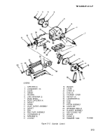
Remove charge pump assembly (8, fig. 3-6) consisting of inner and outer rotor.
Figure 3-5. Charge Pump Upper Valve Plate.
Figure 3-6. Charge Pump Eccentric, Inner and Outer Rotor.
3-10
Back to Top


