TM-5-3895-372-20 - Page 589 of 694
TM 5-3895-372-20
AIR SYSTEM.
11-14. FLUFFER VALVE MAINTENANCE (Continued).
LOCATION/ITEM
ACTION
REMARKS
B. INSPECTION.
5.
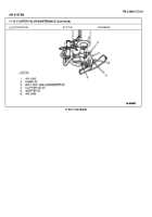
Air lines (1) and (6).
Inspect for damaged lines or
Replace, if necessary.
fittings.
C. INSTALLATION
NOTE
Apply liquid teflon to all threaded joints at installation.
6.
Two elbows (2)
Install in fluffer valve (4).
and adapters (5).
7.
Two bolts. nuts, and
Mount fluffer valve (4) and
Check before mounting valve.
lockwashers (3).
tighten.
Embossed arrow on valve gives
direction of air flow.
8.
Air line (6).
Install and tighten.
Install swivel end last.
9.
Air line (1).
Install and tighten.
Install swivel end last
D. OPERATIONAL CHECK.
10.
Draincocks and air
Close draincocks and open
gate valve.
air gate valve.
11.
Mixer body.
Start up (see TM 9-2320273-
Chassis pressure should be at
10 and TM 5-3895-372-10).
least 65 psi (448 kPa).
12.
Fluffer valve (4) and
Activate fluffer valve (4).
air lines (1) and (6).
Check for leaks
13.
Mixer body.
Shut down. (See TM 9-2320
273-10 and TM 5-3895-372-10).
11-52
Back to Top


