TM-5-3895-372-34 - Page 18 of 120
TM 5-3895-372-34
Table 2-2.
Troubleshooting Procedures (Continued)
MALFUNCTION
TEST OR INSPECTION
CORRECTIVE ACTION
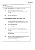
3.
HYDRAULIC OIL PUMP IS NOT DELIVERING OIL (Continued):
Step 4.
Check that oil is proper for climate.
Use correct oil.
(Refer to LO 5-3895-372-12.)
Step 5.
Check for broken pump shaft or internal parts.
Replace damaged parts (para 2-13).
4.
HYDRAULIC OIL PUMP NOT DEVELOPING PRESSURE:
Step 1.
Check whether relief valve is set too low.
Test per TM 5-3895-372-20 and set if too low.
Step 2.
Check whether the relief valve is sticking open.
Test per TM 5-3895-372-20 and, if necessary, repair damaged
valve (para 3-9 thru 3-12).
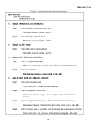
Step 3.
Check whether vane holdout pins are loading vanes.
Disassemble and check pins and
pin bores for burrs or damage.
Check for foreign material (para 3-6 and 3-7).
Step 4.
Check if a free recirculation of fluid to tank is being allowed.
Ensure directional control valve is not in neutral position and that bypass
valve is closed (refer to TM 5-3895-372-10).
Clean or replace bypass valve as necessary (refer to TM 5-3895-372-20).
Repair control valve as necessary (refer to para.
3-14 thru 3-16).
5.
THE HYDRAULIC OIL PUMP IS NOISY OR OPERATION ERRATIC:
Step 1.
Check for air leak at pump inlet or suction lines.
Find leaks by pouring system fluid around joints and listening for change
in sound level.
Tighten as required.
Step 2.
Check for pump body and cover separation.
Make sure bolts are torqued properly (para 2-13).
Step 3.
Check for worn vanes, cam ring, or port plates.
Disassemble according to overhaul instructions and replace worn parts (para 3-6).
Step 4.
Check for worn vane hold out pins or clogged oil feed holes in pins.
Replace pins if worn or clean if clogged (para 3-6).
Step 5.
Check for worn bearings.
Disassemble and replace (para 3-6 thru 3-8).
Change 1
2-5
Back to Top

