TM-5-3990-263-13-P - Page 222 of 728
PERFORM PROCEDURE - Continued
3.
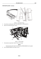
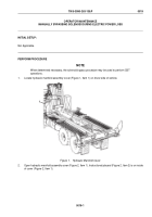
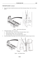
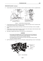
Secure winch frame to the BAP and ensure two winch frame locking levers (Figure 1, Item 1) are in the up
position.
1
2
Figure 1.
Winch Frame Locking Levers.
4.
If locking levers (Figure 1, Item 1) are not up:
a.
Remove lockpin (Figure 1, Item 2) from each locking lever (Figure 1, Item 1).
b.
Swing locking lever (Figure 1, Item 1) to the up position.
c.
Insert lockpin (Figure 1, Item 2) into locking lever (Figure 1, Item 1).
5.
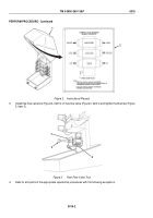
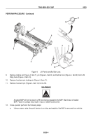
Connect two hydraulic hoses (Figure 2, Item 3) to the stowed location connections (Figure 2, Item 4).
3
4
Figure 2.
Stow Hydraulic Hoses.
TM 5-3990-263-13&P
0020
0020-2
Back to Top

