TM-5-4210-249-13-P-1 - Page 847 of 1188
TM 5-4210-249-13&P-1
0109-9
DRAFT
0109
TFFT02695
Step 13.
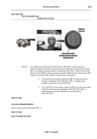
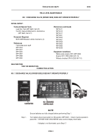
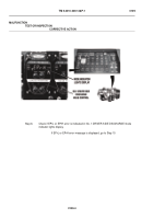
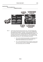
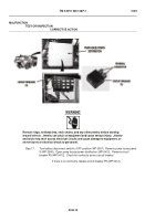
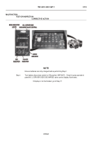
Remove 4 screws and bezel from pump operator’s panel NO. 1 DRIVER SIDE
DISCHARGE valve control.
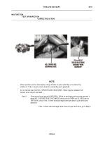
Check for signs of water and moisture damage.
If valve control shows evidence of water and moisture damage, replace NO.
1 DRIVER SIDE DISCHARGE valve control (WP 0417).
Step 14.
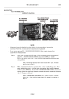
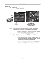
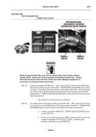
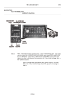
Install 4 screws and bezel on NO. 1 DRIVER SIDE DISCHARGE valve control.
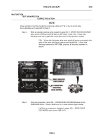
Remove No. 1 driver side discharge valve (WP 0485) and inspect it for binding,
damage, and contamination.
a.
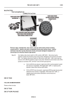
If No. 1 driver side discharge valve is free from binding, damage, and
contamination, reinstall valve (WP 0485) and replace No. 1 driver side
discharge valve motor and drive assembly (WP 0388).
b.
If No. 1 driver side discharge valve is not free from binding, damage,
and contamination, repair (WP 0387) or replace No. 1 driver side
discharge valve (WP 0485).
MALFUNCTION
TEST OR INSPECTION
CORRECTIVE ACTION
Back to Top

