TM-5-5420-202-10 - Page 161 of 535
0022
TM 5-5420-202-10
Communication System
NOTE
• Operation of amplif er AM-1780/VRC and operation of intercom sets are contained in
these work packages.
• Refer to TM 11-5820-498-12 for operation of radio sets AN/VRC-53 and AN/VRC-64.
• Refer to TM 11-5820-401-10-2 for operation of radio set AN/VRC-46.
• Refer to TM 11-5915-224-14 for operation of transient suppressor MX-7778A/GRC.
• Notify f eld maintenance for removal and installation of radio sets.
Amplif er AM-1780/VRC
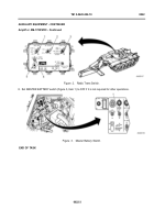
1. Set MASTER BATTERY switch (Figure 1, Item 1) to ON.
Figure 1.
Master Battery Switch.
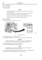
2. Set MAIN PWR switch (Figure 2, Item 1) to NORM.
3. Set POWER CKT BKR (Figure 2, Item 4) to ON. POWER indicator (Figure 2, Item 5) will light.
CAUTION
If POWER CKT BKR (Figure 2, Item 4) trips to OFF after reset, move MAIN PWR switch
(Figure 2, Item 1) to OFF to prevent damage to amplif er. Notify f eld maintenance.
4. If POWER CKT BKR (Figure 2, Item 4) trips to OFF, reset to ON.
5. Move INT ACCENT switch (Figure 2, Item 2) to ON or OFF.
NOTE
INT ACCENT (Figure 2, Item 2) OFF: Intercom and radio sound levels are equal. INT
ACCENT ON: Radio sound level is lower than intercom.
6. Set RADIO TRANS switch (Figure 2, Item 3) to CDR + CREW, CDR ONLY, or LISTENING SILENCE.
7. Turn off amplif er by moving MAIN PWR switch (Figure 2, Item 1) to OFF.
0022-2
AUXILIARY EQUIPMENT
Back to Top

