TM-5-5420-202-20-2 - Page 29 of 734
TM 5-5420-202-20-2
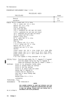
POWERPLANT REPLACEMENT (Sheet 1 of 21)
PROCEDURE INDEX
PROCEDURE
PAGE
Removal
5-2
Installation
5-14
9/16 in. socket with 1/2 in. drive
TOOLS:
7/16 in. socket with 1/2 in. drive
Ratchet with 1/2 in. drive
Flat-tip screwdriver
Long round nose pliers
7/16 in. combination box and open end wrench
11/16 in. combination box and open end wrench
7/8 in. combination box and open end wrench
7/8 in. crowfoot with 3/8 in drive
Diagonal cutting pliers
3/4 in. socket with 1/2 in. drive
Spanner wrench
Pinch bar
5 in. extension with 1/2 in. drive
1-1/2 in. socket with 3/4 in. drive
Ratchet with 3/4 in. drive
Universal joint with 1/2 in. drive
Hammer
Torque wrench with 3/8 in. drive (0-600 lb-in) (0-68 NŽm)
Torque wrench with 1/2 in. drive (0-175 lb-ft) (0-237 NŽm)
Torque wrench with 3/4 in. drive (0-600 lb-ft) (0-813 N m)
Adjustable wrench
5 ton hoist capable of lifting powerplant 12 ft. high
SPECIAL TOOLS
Final drive guide shields (Fig. F-1, Appendix F) (2 required)
Final drive adapter hook-up tool (Fig. F-4, Appendix F)
Engine and transmission sling (Item 32, Chapter 3, Section
I)
SUPPLIES:
Covers for fire extinguisher flexible tubing
Covers for hydraulic brake line openings
Covers for fuel lines openings
Covers for air cleaner hoses and outlets
Grease (Item 37, Appendix D)
Lockwire (Item 61, Appendix D)
Light rope (or heavy masking tape)
Cotter pins
Wooden blocks 12 in. x 12 in.
Lockwashers
PERSONNEL: Three
REFERENCE:
TM 5-5420-202-10
NOTE
Use suitable container to catch fuel whenever any fuel
Iine or connection is loosened or disconnected. Use cloth
to wipe any spillage. Discard cloth and drained fuel in
Go on to Sheet 2
accordance with local procedures.
5-2
Change 3
Back to Top

