TM-5-5420-202-20-2 - Page 50 of 734
TM 5-542-202-20-2
POWERPLANT REPLACEMENT (Sheet 18 of 21)
NOTE
If two place parking brake cable
through 48. If one piece cable is
proceed with step 39.
CAUTION
To prevent bending of control
is used skip steps 39
used skip step 38 and
rod, tighten hex of
quick disconnect only slightly more than finger tight.
36.
37.
38.
39.
40.
41.
42.
43.
45.
46.
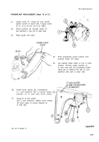
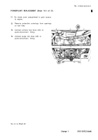
On right side of powerplant, position
steering linkage into connecting link (Q).
Install screw (R) and tighten, using 7/16
inch wrench.
Carefully position (don’t twist) rear cable,
Using 7/8 inch wrench, connect quick-disconnect.
Position parking brake control rod end into
bellcrank clevis.
Push straight pin (S) into holes to secure
rod end to clevis.
Using pliers, install cotter pin (T) into pin
(S).
Position control rod support bracket (U)
to brake control bracket.
Install two lockwashers (V) and screws (W)
to secure support bracket (U).
Install clamp (X), lockwasher (Y), and screw
(Z) to secure control rod cable to power-
plant.
Using 7/16 inch socket, tighten screw (Z).
5-19
Go on to Sheet 19
Back to Top


