TM-5-5420-202-20-3 - Page 194 of 1060
TM 5-5420-202-20-3
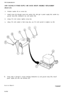
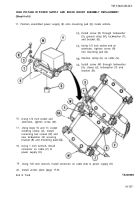
HIGH VOLTAGE IR POWER SUPPLY AND SHOCK MOUNT ASSEMBLY REPLACEMENT
(Sheet 6 of 6)
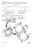
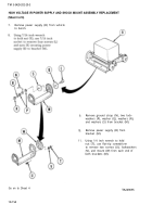
11. Position assembled power supply (K) onto mounting pad (Q) inside vehicle.
16.
17.
18.
19.
20.
End
Install screw (R) through lockwasher
(S), ground strap (M), lockwasher (T),
and bracket (B).
Using 1/2 inch socket and an
extension, tighten screw (R)
into mounting pad (Q).
Position clamp (U) on cable (V).
Install screw (W) through lockwasher
(X), clamp (U), lockwasher (Y) and
bracket (B).
Using 1/2 inch socket and
extension, tighten screw (W).
Using steps 16 and 17, except
omitting clamp (U), install
remaining two screws (W) and
new lockwasher (X) securing
bracket (B) and mounting pads
Using 1 inch wrench, install
connector on cable (Z) to
power supply (K).
Using 7/8 inch wrench, install connector on cable (AA) to power supply (K).
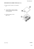
Install access plate (page 17-9).
of Task
TA249098
10-157
Back to Top

