TM-5-5420-202-20-4 - Page 463 of 534
TM 5-5420-202-20-4
MATERIAL
STOCK SIZE
DESCRIPTION
FABRICATING REQUIREMENT
MS3106R10SL4SC
Connector, electrical
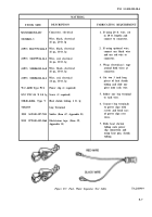
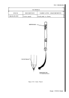
1. If using 20 ft. wire, cut
in 10 ft. lengths and
M1348611-3
Wire, black, electrical
connect to connector.
16 ga., 20 ft. lg
(OPT) M227591/1616-0
Wire, black, electrical
2. If using optional wire,
16 ga., 10 ft. lg
connect one black wire
and one red wire to
(OPT) M22759/16-16-2
Wire, red, electrical
connector.
16 ga., 10 ft. lg
3. Wrap electrician’s tape
(OPT) M81044/12-16-0
Wire, black, electrical
around both wires at
16 ga., 10 ft. lg
connector.
(OPT) M81044/12-16-2
Wire, red, electrical
4. Cut two 3 inch long
16 ga., 10 ft. lg
pieces of heat shrink
tubing and slide one
W-C-440B Type PC4
Power clip (2 required)
piece onto each wire.
8/32 UNC-2A X 1/4 lg
Screw (2 required)
5. Solder one lug terminal
to each wire.
MILR-46846, Type V
Heat shrink tubing, 1 ft. lg
6. Connect lug terminals
7056709
Lug Terminal
to power clips with
screws and bend ears
NSN 3439-00-307-7333
Solder (Item 67, Appendix D)
of power clips over
wires.
NSN 5970-00-419-3164
Electricians tape (Item 59,
Appendix D)
7. Slide heat shrink
tubing onto power
clip connection and
using heat gun, shrink
tubing.
Figure F-7. Fuel- Water Separator Test Cable
TA248939
F-7
Back to Top

