TM-5-5420-228-24 - Page 736 of 750
TM 5-5420-228-24
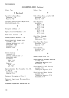
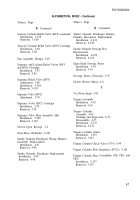
ALPHABETICAL INDEX - Continued
Subject, Page
Subject, Page
Hydraulic Slave Hose Assembly
M
- Continued
Assembly, 3-222
Disassembly, 3-221
Adjustment, 3-76
Installation, 3-91
L
Removal, 3-90
Left Cupola Quadrant
Master Relief Valve (RV1) Cartridge
Installation, 3-40
Installation, 3-73
Removal, 3-39
Removal, 3-73
Lid Assembly Periscope Mount, 3-36
Master Relief Valve-to-Pump Hose Assembly (BA)
Installation, 3-198
Lid, Periscope Mount, 3-28
Removal, 3-197
Lid Latch, Periscope Mount, 3-31
Model Number and Equipment Name, 1-1
Locking Cylinder
O
Assembly, 4-84
Cleaning and Inspection, 4-84
Oil Strainer, Reservoir Quadrant, 3-257
Disassembly, 4-82
Installation, 3-241
Outlet-to-Relief Valve Mount Hose Assembly (CR)
Removal, 3-240
Installation, 3-162
Removal, 3-162
Locking Cylinder Hose Assemblies
(CE1, CE2, and M)
Overhead Cylinder
Installation, 3-153
Assembly, 4-73
Removal, 3-151
Cleaning and Inspection, 4-72
Disassembly, 4-70
Locking Cylinder Hose Assemblies (EA1, CP3, Installation, 3-228
CP4, and CS)
Removal, 3-225
Installation, 3-181
Removal, 3-180
Overhead Cylinder Armor
Installation, 3-224
Locking Relief Valve (RV6)
Removal, 3-223
Adjustment, 3-87
Installation, 3-104
Overhead Cylinder Hose Assemblies (CL, CM, CN
Removal, 3-103
and CO)
Installation, 3-129
M
Removal, 3-125
Maintenance Allocation Chart, B-1
Overhead Cylinder Hose Assemblies, (DA 5 and DA6)
Installation, 3-171
Maintenance Forms, Records and Reports, 1-1
Removal, 3-170
Master Check Valve (CV1), 3-90
Overhead Cylinder Relief Valve (RV3)
Adjustment, 3-81
Master Relief Valve (RV7)
Installation, 3-97
Removal, 3-95
I-4
Back to Top

