TM-5-5420-228-24 - Page 78 of 750
TM 5-5420-228-24
S TEIICE
Test
Procedures
- Continued
DC
VOLTAGE
TEST
NO.
89
-----
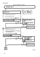
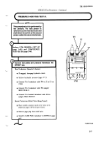
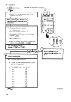
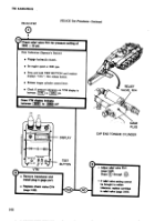
Perform VTM
GENERAL
SET UP (page
2-42)
AND
CONFIDENCE
TEST NO. 66
(page
2-44).
-
‘-
I
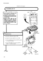
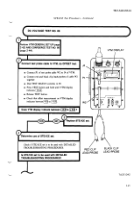
Connect
test
probe
cable
to VTM,
do OFFSET
test.
●
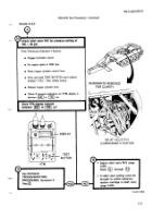
Connect
P 1 of test
probe
cable
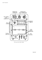
W2 to J4 of V’TM.
●
Connect
red and
black
clip
leads/probes
of cable
W2
together.
●
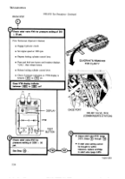
Dial
TEST
SELECT
switches
to 89.
●
Press
TEST
button
and
hold
until
VTM
display
indicates
~].
●
Release
TEST
button.
●
Check
that
otTset measurement
on VTM
display
indicates
between
~
to ~.
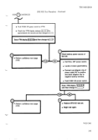
Does
VTM
display
indicate
between
~to
[~]?
m
—
J4
f
1
0
PI
T
@
t
0
W2
I
Replace
STE/lCE
set.
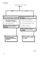
Determine
use of STE/lCE
set.
A
VTM
DISPLAY
/
Check
if STE/ICE
set is to be used
with
DETAILED
/
\
TROUBLESHOOTING
PROCEDURES.
)
RED CLIP
BLACK
CLIP
LEAD/PROBE
LEAD/PROBE
Is STE/lCE
set to be used
with
DETAiLED
TROUBLESHOOTING
PROCEDURES?
TA251
342
2-45
Back to Top


