
TM-5-5420-228-24
LAUNCHER HYDRAULICS SYSTEM M48A5/M60A1 TANK CHASSIS, TRANSPORTING: FOR BRIDGE, ARMORED-VEHICLE-LAUNCHED; SCISSORING TYPE, CLASS 60
TECHNICAL MANUAL; ORGANIZATIONAL, DIRECT SUPPORT AND GENERAL SUPPORT; MAINTENANCE MANUAL
AUGUST 1985

TM-5-5420-228-24 - Page 81 of 750
TM 5-5420-228-24
STEP
2
CONTINUED
STE/ICE
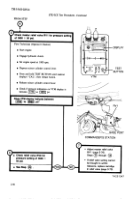
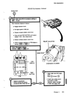
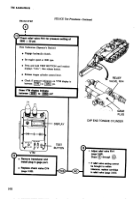
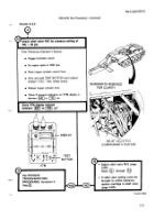
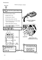
Test
Procedure
- Continued
I
●
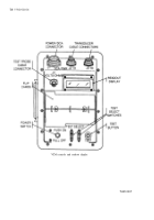
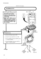
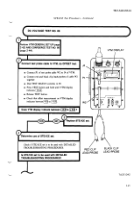
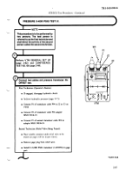
Connect
P2 of second
transducer
cable
W4
to
connector
on
transducer.
L=”””l
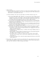
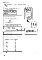
When
performing
the
OFFSET
test,
make sure system
to be tested,
is not
First
●
●
●
●
Technician
(Operator’s
Station)
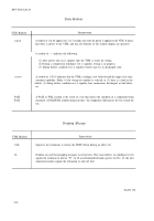
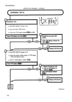
Dial
TEST
SELECT
switches
to 51.
Press
and
hold
TEST
button
until
VTM
display
indicates
~’
Release
TEST
button,
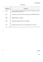
Check
that
OFFSET
measurement
on
VTM
display
indicates
between
-l
to
1~1
Does
VTM
display
indicate
between
[~1
to
[~]
?
&P)
Perform
pressure
test.
I-1.
Perform
OFFSET
FAULT
ISOLATION
(TM
9-4910-571-12
r
First
Technician
(Operator’s
Station)
●
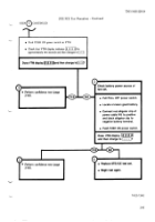
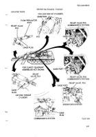
The
next
step
to be performed
depends
on which
relief
valve
is being
tested.
●
FOR
RELIEF
VALVE
- GO
TO
STEP
.
RVI
@
●
RV2
@
.
RV3
@
:
RV4
o
.
RV5
@
●
RV6
@
●
RV8
@
.
RV9
~
TA251
345
2-48

Back to Top


