TM-5-5420-228-24 - Page 90 of 750
TM
5-5420-228-24
FROM
STEP
S7E/ZCE
Test Procedures -
Continued
—
(
--
a
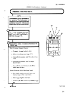
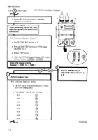
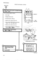
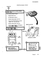
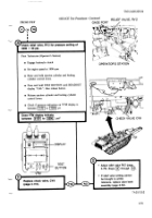
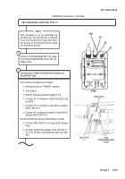
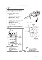
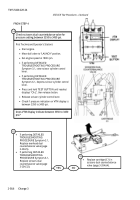
~check relief valve
RV9for presum8dtlng
of
(
3800 *50psl.
\
First Technician
(Operator’s
Station)
●
Disengage hydraulic
clutch.
●
Cycle bridge launchlng
control
levers.
●
Stop engine.
●
Remove trmsduccr
from inlet section of valve bank
and install gage plug.
Both Technicians
(Outside Vehicle)
●
Have
bridge
removed from launcher
(TM 5-5420-203-14).
●
Remove overhead cylinder armor
(page 3-223).
second
Technician
(Overhead
Cylinder)
●
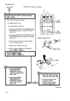
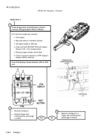
Place suitable fluid container
under
relief
valve
RV9.
●
Remove gage plug from RV9 and install transducer.
First Technician
(operator’s
Station)
●
Start engine.
●
Engage hydraulic
clutch.
●
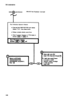
Set engine speed at 1800 rpm.
●
Raise overhead cylinder control
lever.
■
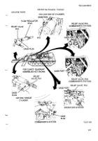
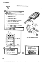
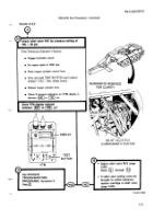
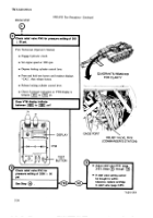
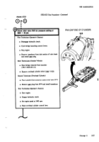
RV9 (CAP END OF CYLINDER)
RV9
.—
Change
2
2-57
Back to Top

