TM-5-5420-228-24 - Page 98 of 750
Change 3
2-58.7/(2-58.8 blank)
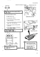
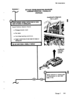
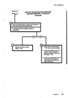
First Technician (Operator's Station)
x
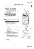
Move ball valve to “TRAVEL” position.
x
Stop engine.
x
Cycle bridge launching control levers.
x
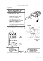
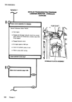
Remove gage plug from inlet section of valve
bank and install transducer.
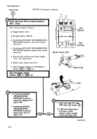
Both Technicians (Outside Vehicle)
x
Have bridge removed from launcher
TM 5-5420-203-14.
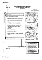
x
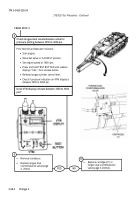
Remove overhead cylinder armor (page 3-
223).
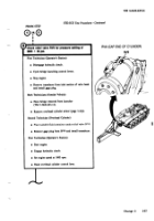
First Technician (Operator's Station)
x
Start engine.
x
Move ball valve to "LAUNCH" position.
x
Set engine speed at 1800 rpm.
x
Raise overhead cylinder control lever.
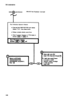
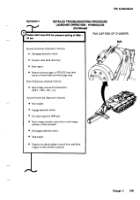
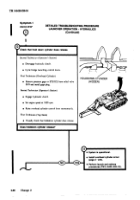
First Technician (Operator's Station)
x
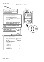
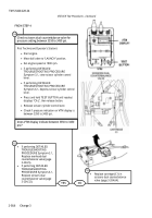
Press and hold TEST BUTTON until readout
displays "CAL", then release button.
x
Release overhead cylinder control lever.
x
Check if pressure indication on VTM display is
between 3550 to 3650 psi.
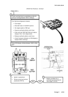
Check overhead dual counterbalance valve for
pressure setting between 3550 to 3650 psi.
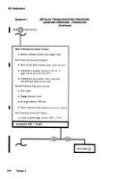
Does VTM display indicate between 3550 to 3650
psi?
17
FROM STEP 4
x
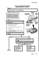
Return to DETAILED
TROUBLESHOOTING
PROCEDURES, Symptom-
1.1, Step 10.
x
Replace cartridge (C2) in
overhead dual counterbalance
valve (page 3-204.64).
YES
NO
TM 5-5420-228-24
STE/ICE Test Procedures - Continued
18
19
Back to Top

