TM-9-1240-401-34-P - Page 164 of 590
4-50
TM 9-1240-401-34&P
4-24. M145/M145A1 TELESCOPE MOUNT FINAL INSPECTION AND ADJUSTMENT
- continued
a. SETTING UP AND ADJUSTING THE CROSS-LEVELING FIXTURE - continued
10
11
12
13
14
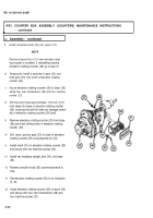
Mount setup gage (10) on fixture adapter (6), and
secure with four mounting bolts (11).
Install collimating telescope (12) in setup gage
(10). Snug up thumbscrews (13) securing
collimating telescope (12); do not tighten at this
time.
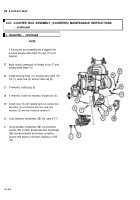
Suspend a plumb line approximately 25 feet
(7.62m) directly in front of collimating telescope
(12).
Revolve collimating telescope (12) until its vertical
line is superimposed on plumb line. Tighten thumb-
screws (13) holding collimating telescope (12).
Fabricate rigidity test target (14). Use the following
formula for target fabrication of test target:
TARGET DISTANCE
1 MIL GRADUATION
= (IN INCHES )
1000
GIVEN:
TARGET DISTANCE = DISTANCE FROM
SIGHTING DEVICE TO PLACEMENT OF
TARGET.
EXAMPLE:
1 MIL
= 50 FT x 1 2 IN/FT = 0.6 IN
GRADUATION
1000
0.25 MIL = 0.6 IN X 0.25 = 0.15 IN
1.50 MIL = 0.6 IN X 1.50 = 0.9 IN
Back to Top


