TM-9-1240-401-34-P - Page 157 of 590
TM 9-1240-401-34&P
NOTE
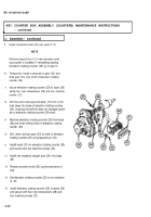
Perform steps 16 thru 24 if new correction ro-
tating counter is installed. If reinstalling exist-
ing correction rotating counter, go to step 23.
16 Temporarily install a setscrew in gear (26) and
slide gear onto shaft of correction rotating counter
(22).
17 Secure correction rotating counter (22) on base
(36) using four new Iockwashers (21) and four ma-
chine screws (20).
18 Drill two pilot holes approximately 1/16 inch (0.16
mm) deep into base of correction rotating counter
(22) ensuring that drill bit does not damage numer-
als or correction rotating counter (22) shaft.
19 Remove correction rotating counter (22) from base
(36) and finish drilling holes in correction rotating
counter (22).
20 Drill, ream, and pin gear (26) to shaft of correction
rotating counter (22) using tapered pin (25).
21 Install mask (24) on correction rotating counter (22)
and secure with two machine screws (23).
22 Install two headless straight pins (34), in base (36).
23 Rotate shaft (37) counterclockwise to stop. Set cor-
rection rotating counter (22) to a reading of 9948.
24 Install correction rotating counter (22) on base (36)
and secure with four new Iockwashers (21) and
four machine screws (20).
4-4 3
Back to Top


