TM-9-1240-401-34-P - Page 152 of 590
TM 9-1240-401-34&P
4-20. COUNTER BOX ASSEMBLY MAINTENANCE INSTRUCTIONS - continued
d. Assembly - continued
8
9
10
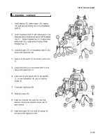
Insert lamp base potion of overlay assembly (29)
into electrical lead (33). Position wire (30) in
recessed area to accommodate protective cap (28).
Apply adhesive to inside edge of protective cap (28).
Install protective cap (28) and secure with two
machine screws (27). Remove excess adhesive
from outer edge of protective cap (28).
e. Installation
1
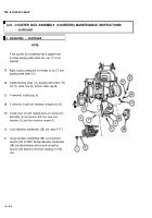
Install eccentric stud (22) and setscrew (21).
2
Set the correction counter (41) and elevation
counter (42) to 0.
3
Apply sealing compound around keyways and slot
around eccentric stud (22), and install counter box
assembly (20) on M145/M145A1 telescope mount
using four flat washers (19), four new lockwashers
(18), and four nuts (17). Hand tighten four nuts (17).
4
Loosen setscrew (21) and rotate eccentric stud (22)
to obtain minimum backlash in the elevation
handwheel (43). Tighten setscrew (21).
5
Tighten four nuts (17).
4-38
Change 1
Back to Top


