TM-9-1240-401-34-P - Page 150 of 590
TM 9-1240-401-34&P
4-20. COUNTER BOX ASSEMBLY MAINTENANCE INSTRUCTIONS
This task covers:
a. Removal b. Disassembly
c. Repair d. Assembly e. Installation
Tools
INITIAL SET-UP
Lockwashers (3) (Item 68, appx E)
Lockwashers (4) (Item 71, appx E)
Tool Kit, Electronic System, Repair, Field Mainte-
Sealing compound (Item 13, appx B)
nance (SC5180-95-CL-B29)
Tubular spanner wrench, 11/16 and 45/64 inch
TM 9-254
(Item 26, appx F)
TM 750-116
Materials/Parts
Adhesive (Item 2, appx B)
M145/M145A1 telescope mount removed
Lockwashers (8) (Item 63, appx E)
from howitzer (TM 9–2350-311-20-2/
Lockwashers (4) (Item 64, appx E)
TM 9–2350-314-20-2)
a. Removal
1
2
3
5
6
7
4-36
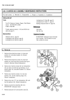
Remove three machine screws (1), three lock-
washers (2), and plate insulator (3). Discard
Iockwashers.
Remove three machine screws (4), three lock-
washers (5), and three wires (6) with three lug ter-
minals (7) attached. Discard Iockwashers.
Remove two machine screws (8), two Iockwashers
(9), two wires (10) with two lug terminals (11) at-
tached, plate (12), and plate insulator (13). Discard
lockwashers.
Remove two machine screws (14), two lock-
washers (15), and two retaining straps (16).
Discard Iockwashers.
Remove four nuts (17), four Iockwashers (18), and
four flat washers (19). Discard Iockwashers.
Remove counter box assembly (20) from
M145/M145A1 telescope mount.
Remove setscrew (21) and eccentric stud (22).
4
Back to Top


