TM-9-1240-401-34-P - Page 141 of 590
TM
9-1240-401-34&P
c. Assembly
I
1
2
3
4
5
6
7
8
9
10
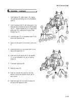
Install knob (32) and tapered pin (31) on M145
telescope mount.
Install knob (34) and spring pin (33) on M145A1
telescope mount.
Install cover (30) between bosses of rocker assem-
bly and slide level (29) into position
Install control cam (28), holder (27), and threaded
ring (26), using fabricated eccentric tool. Do not
tighten, pending final adjustment.
Install lens (25) and electrical lead (24) with raised
brass portion facing outward.
Apply sealing compound to threads of threaded
ring (23).
Using 11/16 and 45/64 inch tubular spanner
wrench, install threaded ring (23). Stake threaded
ring (23) in three places.
Install LED (22), electrical connector cover (21 ),
new Iockwasher (20), and machine screw (1 9).
Install clamp (18), new Iockwasher (17), machine
screw (16), new Iockwasher (1 5), and machine
screw (14).
Install two retaining straps (13), two new lock-
washers (12), and two machine screws (11 ).
4-27
Back to Top


