TM-9-1240-401-34-P - Page 136 of 590
TM 9-1240-401-34&P
4-15. LEVEL ASSEMBLY MAINTENANCE INSTRUCTIONS - continued
I
b. Disassembly
I
2
3
4
5
6
7
8
9
10
11
12
13
14
15
16
1
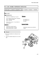
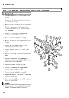
Remove threaded ring (4), using fabricated eccen-
tric tool.
Remove cell (5); slide cross-level (6) from bracket
(7) and remove cover (8).
Remove headless straight pin (9), only if damaged.
Remove machine screw (10), Iockwasher(11 ),
electrical connector cover (12), and LED (13). Dis-
card Iockwasher.
Using 11/1 6 and 45/64 inch tubular spanner
wrench, remove threaded ring (14).
Remove electrical lead (15) and lens (16).
Remove threaded ring (17) using fabricated eccen-
tric tool.
Remove cell (18); slide pitch level (19) from
bracket (7) and remove cover (20).
Remove headless straight pin (21), only if dam-
aged.
Remove window (22), only if necessary for replace-
ment.
Remove machine screw (23), Iockwasher (24),
electrical connector cover (25), LED (26), and ring
spacer (27). Discard Iockwasher.
Remove ring spacer (27) from LED (26).
Using 11/1 6 and 45/64 inch tubular spanner
wrench, remove threaded ring (28).
Remove electrical lead (29) and lens (30).
Remove two rivets (31 ) and mirror (32), only if nec-
essary for replacement.
Remove two rivets (33) and mirror (34), only if nec-
essary for replacement.
c. Repair
I
1
Remove corrosion, grease, and dirt from all parts.
Refer to TM 9-254 for cleaning instructions.
4-22
Back to Top


