TM-9-1240-401-34-P - Page 130 of 590
TM 9-1240-401-34&P
4-13. M145/M145A1 TELESCOPE MOUNT MAINTENANCE INSTRUCTIONS - continued
I
c. Assembly - continued
17
18
19
20
21
22
23
24
25
26
27
28
29
30
31
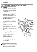
Securely tighten cross-level mechanism knob (79).
With torque wrench and torque adapter (8599917),
rotate cross-level mechanism knob (79) one turn
clockwise and one turn counterclockwise.
Measure the torque required to turn cross-level
mechanism knob (79). Adjust plug (72) to obtain 3
to 6 pound-inches (0.34 to 0.68 N-m) torque.
Install two lug terminals (59) with two wires (58)
attached on plate (60) using two machine screws
(57).
Assemble plate (60) between plate insulator (56)
and plate insulator (55) and install on Ml 45/
Ml 45A1 telescope mount using two new lock-
washers (54) and two cap screws (53).
Install insulator (52), if removed.
Install two lug terminals (49) with wires (50) at-
tached on two contacts (51) with two nuts (48).
Install receptacle shell (47), plate (46), shoulder pin
(45), and machine screw (44).
Install lug terminal (40) with attached wire (41 ) us-
ing new Iockwasher (39) and cap screw (38).
Using solder and flux, solder wire (36) and wire
(37) to toggle switch (33) (ref. TM 9-254).
Install plate (32) on toggle switch (33) using wash-
er (35) and nut (34).
Install toggle switch (33) and plate (32) on mount
using three machine screws (31 ).
Install retaining strap (30), new Iockwasher (29),
and machine screw (28).
Install two retaining straps (27), two new lock-
washers (26), and two machine screws (25).
Install two clamps (43) and two machine screws
(42).
4-16
Back to Top


