TM-9-1240-401-34-P - Page 127 of 590
TM9-1240-401-34&P
19
20
21
22
23
24
25
26
27
28
29
30
31
32
33
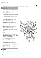
Using a feeler gage, check the clearance between
the cross-level mechanism (61) and the rocker as-
sembly above the cross-level mechanism. Record
the reading for use during installation of the cross-
Ievel mechanism (61) later.
Loosen nut (62) until it is flush with the end of ta-
pered pin (63).
Tap nut (62) until sleeve bearing (64) and tapered
pin (63) disengage.
Remove nut (62), sleeve bearing (64), and tapered
pin (63) as a unit.
Remove two cap screws (65), two Iockwashers
(66), two cap screws (67), and two Iockwashers
(68). Discard Iockwashers.
Tilt cross-level mechanism (61 ) forward until it
clears rocker assembly and remove cross-level
mechanism (61).
Remove two clamping catches (69) by removing
two machine screws (70) and two Iockwashers (71)
for each clamping catch (69). Discard Iockwashers.
Remove plug (72), spring (73), and V-bearing (74).
Remove gib key (75) and, if necessary, headless
straight pin (76).
Remove two machine screws (77), two lock-
washers (78), cross-level mechanism knob (79),
and indicator (80). Discard Iockwashers.
Remove tapered pin (81), body hub (82), and flat
washer (83).
Remove setscrew (84) and setscrew (85).
Using adjustable spanner wrench, remove seat
(86).
Remove wormshaft assembly (87) from cross-level
mechanism (61).
If necessary for repair, remove three setscrews
(88) and three setscrews (89).
4-13
Back to Top


