TM-9-1240-401-34-P - Page 132 of 590
TM 9-1240-401-34&P
4-14. DISK ASSEMBLY MAINTENANCE INSTRUCTIONS - continued
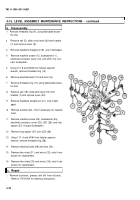
[a. Disassembly
1
1
2
3
4
5
6
7
8
9
10
11
12
13
14
15
16
Remove threaded ring (1) using fabricated eccen-
tric tool.
Remove cell (2).
Slide level (3) out of disk assembly (4), and remove
cover (5).
Remove two machine screws (6 and 7) and two
Iockwashers (8 and 9). Discard Iockwashers.
Remove plate insulator (10) and access cover(11)
with related parts.
Unsolder wire (12) from lug terminal (13).
Remove machine screw (14), Iockwasher (1 5), and
hub clamp (16). Discard Iockwasher.
Remove machine screw (17), lug terminal (13), and
plate (18) from access cover (11 ).
Remove three machine screws (19), three lock-
washers (20), and three retaining straps (21 ). Dis-
card Iockwashers.
Remove machine screw (22), Iockwasher (23), and
electrical cover (24). Discard Iockwashers.
NOTE
Old disk assemblies contain lamps in place of
LEDs.
Remove LED (25).
Using 11/16 and 45/64 inch tubular spanner
wrench, remove threaded ring (26).
Remove electrical lead (27).
Remove two machine screws (28) and reflector
(29), only if necessary for replacement.
Remove tapered pin (30), only if damaged.
Remove two rivets (31 ) and mirror (32), only if nec-
essary for replacement.
4-18
Back to Top


