TM-9-1240-401-34-P - Page 142 of 590
TM 9-1240-401-34&P
4-16. QUADRANT SUPPORT ASSEMBLY MAINTENANCE INSTRUCTIONS - continued
I
I Assembly - continued
I
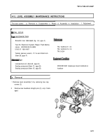
11 Install
plate (7), two lug terminals (6), and two ma-
chine screws (5).
12 Install plate insulator (4), plate insulator (3), two
new lockwashers (2), and two machine screws(1).
13 Install V-bearing (10), spring (9), and retainer (8)
on M145A1 telescope mount.
d. Adjustment
I
2
3
4
5
6
7
8
9
10
1
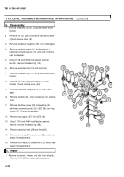
Clamp a 3/8-x 3/4-x 6-inch parallel bar to quad-
rant seat of bracket parallel to the quadrant supporl
assembly level (29).
Position a zeroed M1A1 gunner's quadrant (35) on
parallel bar, parallel to level (29).
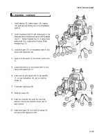
Adjust quadrant support assembly level knob (34)
until M1A1 gunner’s quadrant (35) level (36) bub-
ble is centered.
Loosen threaded ring (26) using fabricated eccen-
tric tool.
Apply sealing compound to threaded ring (26) and
install threaded ring (26) in bracket.
Engage fabricated eccentric tool into holder (27)
and threaded ring (26).
Insert a common straight blade screwdriver
through the center hole in the fabricated eccentric
tool and engage control cam (28).
Adjust control cam (28) and holder (27) until the
level (29) bubble is centered within the graduations
on the level (29).
Rotate level assembly from 0 to 1330 mils and ad-
just control cam (28) and holder (27) until the level
(29) bubble is centered within the graduations on
the level (29).
Rotate level assembly from 1330 roils to 0 and ad-
just control cam (28) and holder (27) until the level
(29) bubble is centered within the graduations on
the level (29).
4-28
Back to Top


