TM-9-1240-401-34-P - Page 151 of 590
TM 9-1240-401-34&P
6
7
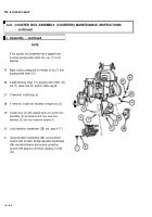
b. Disassembly
1
2
3
4
5
Remove four machine screws (23), four lockwash-
ers (24) and identification plates (25 and 26) from
counter box assembly (20). Discard lockwashers.
Remove two machine screws (27) and protective
cap (28) from overlay assembly (29).
Pull wire (30) with lamp base through to the front of
the overlay assembly (29).
Using 11/16 and 45/64 inch tubular spanner wrench,
remove optical retaining ring (31) and overlay
assembly (29) from counter box assembly (20).
Using 1/2 and 33/64 inch tubular spanner wrench,
remove externally threaded ring (32), electrical lead
(33), and lens (34) from counter box assembly (20).
Remove machine screw (35), lockwasher (36), and
electrical connector cover (37). Discard lockwasher.
Using 11/16 and 45/64 inch tubular spanner wrench,
remove externally threaded ring (38), electrical lead
(39), and lens (40).
c. Repair
1
Remove corrosion, grease, and dirt from all parts.
Refer to TM 9-254 for cleaning instructions.
2
Visually inspect for missing or damaged parts.
3
Repair or replace parts in accordance with authorized parts listed in appendix D.
d. Assembly
1
2
3
4
5
6
7
Install lens (40) and electrical lead (39) with brass portion facing outward.
Apply adhesive to threads of externally threaded ring (38) and install in counter box assembly (20), using 11/16 and
45/64 inch tubular spanner wrench.
Install electrical connector cover (37), new lockwasher (36), and screw (35) to counter box assembly (20).
Install lens (34) and electrical lead (33) to counter box assembly (20).
Using 1/2 and 33/64 inch tubular spanner wrench, install externally threaded ring (32) to overlay assembly (29) and
stake with adhesive.
Pull wire (30) with lamp base through to the front of overlay assembly (29) and position onto counterbox assembly (20).
Install retaining ring (31) to overlay assembly (29).
Install identification plates (25 and 26), using four new lockwashers (24), and four machine screws (23) with adhesive
applied to screw threads.
Change 1
4-37
Back to Top


