TM-9-1240-401-34-P - Page 146 of 590
TM 9-1240-401-34&P
4-19. M145/M145A1 TELESCOPE MOUNT MAINTENANCE INSTRUCTIONS
I This task covers:
a. Disassembly b. Repair c. Assembly
lTIAL SET-UP
Tool Kit, Electronic System, Repair, Field Mainte-
nance(SC5180-95-CL-B29)
TM 9-254
.
aterials/Parts
. .
ment Condition
Grease (Item 6, appx B)
Lockwashers (10) (Item 68, appx E)
M145/M145A1 telescope mount removed
Oil, lubricating (Item 9, appx B)
from howitzer (TM 9-2350-311-20-2/
Sealing compound (Item 13, appx B)
TM 9-2350-314-20-2)
Self-locking nut (Item 12, appx E)
Self-locking nut (Item 16, appx E)
Counter box assembly removed (ref. para 4-20)
1
a. Disassembly
I
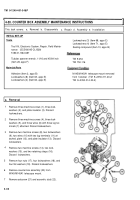
1 Drive out tapered pin (1); remove pitch knob (2)
and flat washer (3) from shouldered shaft (4).
2 Remove six machine screws (5), six Iockwashers
(6), six flat washers (7), and cover (8). Discard
Iockwashers.
3 Drive out tapered pin (9) from bevel gear (10) and
shouldered shaft (4).
4 Remove threaded ring (11) and slide out shoul-
dered shaft (4) and related parts. Remove bevel
gear (10) from shouldered shaft (4).
5 Remove self-locking nut (12), bearing (13), sleeve
spacer (14), and bearing (15) from shouldered
shaft (4). Discard self-locking nut.
6 Remove plug (16), spring (17), and V-bearing (18).
7 Remove setscrew (19).
4-32
Back to Top


