TM-9-1240-401-34-P - Page 169 of 590
TM 9-1240-401-34&P
f. PITCH ADJUSTMENT
1
2
3
4
5
6
7
8
9
10
11
12
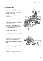
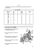
Install perpendicularity gage (1) or use two parallel
bars on M145/M145A1 telescope mount (2).
Level cross-leveling fixture (3) in elevation and
cross-level (ref. para
4-24a).
Set M1A1 gunner's quadrant (4) on perpen-
dicularity gage (1).
Adjust the pitch knob (5) to center the M1A1 gun-
ner’s quadrant level (6).
Engage fabricated eccentric tool (fig. C-3, appx C)
to the threaded ring (7).
Insert a common straight blade screwdriver
through center hole in fabricated eccentric tool (fig.
C-3, appx C) and engage cell (8).
Adjust cell (8) until level (9) bubble is centered
within the graduations on pitch level (9).
Hold cell (8) firmly in place while turning fabricated
eccentric tool (fig. C-3, appx C) to tighten
threaded ring (7). Be careful not to disturb the set-
ting of pitch level (9).
Mark the pitch knob (5) and bracket using tape as
an open end point for checking backlash.
Rotate pitch knob (5) one revolution clockwise and
return.
Read backlash using M1A1 gunner's quadrant (4)
by centering bubble and reading the error on the
M1A1 gunner’s quadrant (4). Backlash shall not
exceed 1 mil total. If backlash exceeds 1 mil, per-
form step 4 again.
Purge counter box assembly (ref. TM 750-116).
4-55
Back to Top

