TM-9-1240-401-34-P - Page 174 of 590
TM 9-1240-401-34&P
4-24. M145/M145A1 TELESCOPE MOUNT FINAL INSPECTION AND ADJUSTMENT
- continued
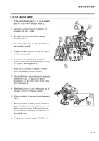
m. CHECKING PITCH KNOB RUNNING TORQUE
With torque wrench (Item 36, appx F) and adapter
(8599912) (Item 5, appx F), rotate pitch knob (1)
one turn clockwise and one turn counterclockwise.
Measure the torque required to turn pitch knob (1).
The torque must be between 5 and 16 pound-
inches (0.56 and 1.80 N-m). If not, repair accord-
ing to repair procedure (ref. para 4-19).
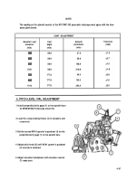
n. CORRECTION COUNTER INSPECTION
2
3
4
5
6
7
8
1
Place M1A1 gunner's quadrant (1) in position on
quadrant support assembly (2).
Set correction counter (3) to +1 mil.
Set elevation counter (4) to 0.
Rotate fixture elevation handwheel (5) on the
cross-leveling fixture (6) until elevation level bubble
is centered.
Note reading on gunner’s quadrant (1).
The quadrant support assembly must elevate or
depress within 0.5 mil of the +1 mil entered into the
correction counter (3).
Repeat steps 2 thru 6 above for correction counter
(3) indications of -1 mil, ±12 mils, ±27 mils, and
±50 mils.
Check alinement of digits in correction counter (3)
and elevation counter (4) by placing the lowest digit
of each counter in coincidence with its respective
line. The alinement of the other counter digits must
not vary more than 1/16 inch (0.16mm). If the digit
alinement varies more than 1/16 inch (0.16mm),
repair according to repair procedure (ref. para
4-17).
4-60
Back to Top


