TM-9-1240-401-34-P - Page 200 of 590
TM 9-1240-401-34&P
I
5-17. M117/M117A2 PANORAMIC TELESCOPE MAINTENANCE INSTRUCTIONS
This task covers:
a. Disassembly b. Repair c. Assembly
INTIAL SET-UP
TooI
S
Soldering iron (Item 24, appx F)
Tool Kit, Electronic System, Repair, Field Mainte-
nance (SC5180-95-CL-B29)
V-block (Item 25, appx F)
Adhesive (Item 2, appx B)
Felt mechanical washer (Item 2, appx E)
Flux (Item 5, appx B)
Grease (Item 6, appx B)
Grease (Item 7, appx B)
Lockwashers (6) (Item 70, appx E)
Preformed packing (Item 31, appx E)
Preformed packing (Item 34, appx E)
Preformed packing (Item 33, appx E)
Sealing compound (Item 13, appx B)
Self-locking nut (Item 17, appx E)
Solder (Item 18, appx B)
M117/M117A2 panoramic telescope removed
from howitzer (TM 9-2350-311-10/
TM 9-2350-314-10)
Equipment Condition
a. Disassembly
I
1
2
3
4
5
6
7
8
9
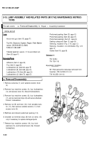
Remove two machine screws (1) and plate (2).
Using azimuth knob, slowly rotate cap (3) and re-
move 50 balls (4).
Pull cap (3) from M117/M117A2 panoramic tele-
scope.
Remove azimuth knob (ref. para 5-13).
Remove plate and gunner's aid knob (ref. para
5-13).
Remove correction counter cover (ref. para 5-13).
Remove elevation knob (ref. para 5-13).
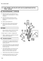
Remove cap screw (5) and Iockwasher (6). Discard
Iockwasher.
Remove cap screw (7) and Iockwasher (8). Discard
Iockwasher.
5-26
Back to Top


