TM-9-1290-365-24-P - Page 218 of 334
ARMY TM 9-1290-365-24&P
D.4.13.7 TRANSMITTED FREQUENCY FAILURE. Failure in test procedure para. D.4.12.3.5.
a. Remove connector P3 from MVP CCA. Check for short circuit between pins 11 and 12 of
connector P3 of EMI filter module. If failed, replace EMI filter module lAW Section D.8.
b. Check for short circuit between pins 11 and 12 of connector P3 of MVP CCA. If failed, test and
troubleshoot MVP CCA lAW Section D.7.
c. If not failed, test and troubleshoot MVP CCA lAW Section D.7.
D.4.13.8 REMOTE CONTROL FAILURE. Failure in test procedure para. D.4.12.3.6.
D.4.13.8.1 No Communication.
a. Remove connector P3 from MVP CCA. Check for continuity, or short circuit, between pin 7 to pin
E, and pin 5 to pin F, of connectors P3 and J1 of the EMI filter module. If failed, replace EMI filter
module lAW Section D.8.
b. Remove connector P4 from MVP CCA. Check for continuity between pin 26 to pin 15 on connector
P4 of harness. Check for continuity between pin 8 to pins 21, 22, 24, 25 on connector P4 of
harness. Check for continuity between pin 13 to pins 11,12,23, on connector P4 of harness. If
failed, repair wiring.
c. If not failed, test and troubleshoot MVP CCA lAW Section D.7.
D.4.13.8.2 Operational Failure. If failure true in test procedure para. D.4.12.3.6b or false or no mea-
surement in test procedure para. D.4.12.6h., k., and n., test and troubleshoot MVP CCA lAW Section D.7.
D.4.14 Final Testing.
D.4.14.1 FINAL TESTING PROCEDURES. The final testing is performed on a reassembled UUT. The
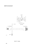
test setup provided in Figure D-11., shows the equipment used and cable hookup for the first procedural
step.
D.4.14.2 TEST DATA SHEETS. The test data sheets in Table D-6, are to be reproduced locally, as
required, for recording the test results. The test data sheets must be completed each time a test section is
performed. The completed test data sheets shall be retained.
D.4.14.3 PREPARATION FOR TEST.
a. Reassemble the UUT lAW para. D.4.11 .9.
b. Energize power supply and adjust for +28 ± 0.5 Vdc. Deenergize power supply.
c. Energize and adjust DMM to measure high DC current.
d. Place the test Doppler simulator on the transceiver antenna radome using the handle.
e. Set test Doppler simulator switch PS/BAT to PS position.
f.
Set test Doppler simulator switch EXTERNAL/INTERNAL to INTERNAL position.
g. Before connecting the UUT to the test setup, verify that both power supplies are deenergized.
h. Connect the UUT to the test setup lAW Figure D-11.
D.4.14.4 FINAL TESTING. Perform the final testing lAW para. D.4.12.3.4 through D.4.12.3.7.
D-48
Back to Top


