TM-9-2320-209-34-2-3 - Page 473 of 592
TM 9-2320-209-34-2-3
e. Replacement.
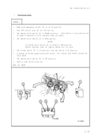
FRAME 1
1.
Aline screw holes in control box assembly (1) with screw holes in instrument
panel (2).
2.
Put in two capscrews and lockwashers (3) and two nuts and washers (4).
3.
Slide in control box panel (5). Put in two screws (6).
4.
Plug in electrical lead sockets (7).
5.
Aline pins on electrical plug (8) and plug it into socket (9) on back of control
box assembly (1). Put in nut (9).
END OF TASK
21-138
Back to Top


