TM-9-2320-260-34-1 - Page 112 of 657
TM 9-2320-260-34-1
3-20. OIL PAN MAINTENANCE
THIS TASK COVERS:
a. Removal
d. Assembly
b. Disassembly
e.
Installation
c. Cleaning and Inspection
INITIAL SETUP
APPLICABI.E MODELS
MATERIALS/PARTS (Contd)
All
Sealing compound (Appendix C, Item 43)
Antiseize tape (Appendix C, Item 50)
TOOLS
General mechanic’s tool kit
(Appendix B, Item 1)
REFERENCES (TM)
LO 9-2320-260-12
Torque wrench, 3/8-in. dr.
TM 9-2320-260-20
(Appendix B, Item 4)
TM 9-2320-260-34P-1
MATERIALS/PARTS
EQUIPMENT CONDITION
Gasket (Appendix D, Item 67)
• Engine oil drained (TM 9-2320-260-20).
Gasket (Appendix D, Item 111)
• Engine oil pan shroud removed (if so equipped)
Gasket (Appendix D, Item 63)
(TM 9-2320-260-20).
Forty lockwashers (Appendix D, Item 217)
Four lockwashers (Appendix D, Item 247)
a. Removal
1.
2.
3.
4.
5.
6.
7.
8.
NOTE
• Have drainage container ready to catch engine oil.
• Engine oil pan is mounted with screw-assembled washers on late
model engine.
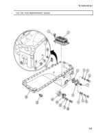
Remove oil return hose (1) from aerator (14) and allow oil to drain completely.
Remove oil pickup hose (22) from suction flange (13).
Remove front sump tube (19) from adapter (18).
Remove oil dipstick tube (3) from adapter (8).
Remove two screws (26), lockwashers (25), washers (24), clamps (23), oil pickup hose (22), and oil
return hose (1) from oil pan (12). Discard lockwashers (25).
Remove four screws (11), lockwashers (10), and washers (9) from rear of oil pan (12) and cylinder
block (21). Discard lockwashers (10).
Remove seven screws (6), lock washers (5), and washers (4) from oil pan (12) and flywheel hous-
ing (2). Discard lockwashers (5).
Remove thirty-eight screws (15), lock washers (16), washers (17), oil pan (12), and gasket (7) from
cylinder block (21) and front gearcase cover (20). Discard lockwashers (16) and gasket (7).
3-60
Back to Top


