TM-9-2320-260-34-1 - Page 240 of 657
TM 9-2320-260-34-1
3-58. FLYWHEEL HOUSING INSTALLATION
THIS TASK COVERS:
a. Installation
b. Alinement
lNITIAL SETUP
APPLICABLE MODELS
MATERIALS/PARTS
All
Gasket (Appendix D, Item 75)
Gasket (Appendix D, Item 77)
TOOLS
Nine packings (Appendix D, Item 305)
General mechanic’s tool kit
(Appendix B, Item 1)
Sixteen lockwashers (Appendix D, Item 219)
Chalk (Appendix C, Item 7)
Dial indicator attachment
(Appendix B, Item 85)
Antiseize tape (Appendix C, Item 50)
Dial indicator (Appendix B, Item 11)
REFERENCES (TM)
Soft-head hammer (Appendix B, Item 47)
TM 9-2320 -260-34P-1
Torque wrench, 3/8-in. dr.
(Appendix B, Item 4)
Drill and reaming fixture
(Appendix B, Item 93)
Electric drill (Appendix B, Item 64)
a. Installation
1.
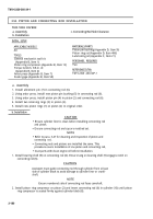
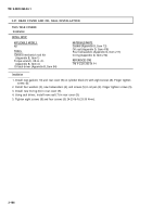
Install new gasket (3) on flywheel housing (2).
2. Install new gasket (4) and access cover (5) on flywheel housing (2) with two screws (6).
3. Wrap male threads of two pipe plugs (1) with antiseize tape and install pipe plugs
(1) on flywheel
housing (2).
NOTE
Perform steps 4 and 5 if dowel pins were removed.
4. Using drill and reaming fixture, ream two holes (13) to next oversize.
5. Install two new dowel pins (12) in cylinder block (7). Ensure new dowel pins (12) are even with or up
to 0.010 in. (0.25 mm) below surface of flywheel housing (2) when installed.
NOTE
Assistant will help with step 6.
6. Install flywheel housing (2) on dowel pins (12) and cylinder block (7) with nine new packings (8),
sixteen washers (9), new lockwashers (10), and screws (11). Finger tighten screws ( 11).
b. Alinement
1.
2.
3.
4.
5.
6.
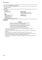
Attach dial indicator to crankshaft ( 15) with dial indicator attachment and position plunger against
flywheel inner face (14).
Mark flywheel housing (2) with chalk at 3, 6, 9, and 12 o’clock positions.
Rotate crankshaft (15) until dial indicator plunger is at 3 o’clock. Zero dial indicator.
Turn crankshaft (15) clockwise one rotation. Record highest reading.
Turn crankshaft (15) until dial indicator is at the point where highest reading occurred. Set dial
indicator to 1/2 highest reading.
Using a soft-head hammer, tap on flywheel housing (2) until dial indicator reads zero. Loosen
screws (11) slightly if necessary. Finger tighten screws(11) when finished. Flywheel housing (2)
is vertically alined.
3-188
Back to Top


