TM-9-2320-260-34-1 - Page 348 of 657
TM 9-2320-260-34-1
5-11. FLOW TEST
THIS TASK COVERS:
a. Test Stand Setup
c. Fuel Delivery Adjustment and Measurement
b. Check Ball Seating Test
INITIAL SETUP
APPLICABLE MODELS
All
SPECIAL TOOLS
Adjusting wrench (Appendix B, Item 154
Locknut wrench (Appendix B, Item 25)
TEST EQUIPMENT
Injector test stand (Appendix B, Item 26)
Test stand link (Appendix B, Item 27)
MATERIALS/PARTS
Retaining ring (Appendix D, Item 342)
Screen (Appendix D, Item 377)
MATERIALS/PARTS (Contd)
Gasket (Appendix D, Item 117)
Orifice plug (Appendix D, Item 321)
Diesel fuel (Appendix C, Item 13)
REFERENCES (TM)
TM 9-2320-260-10
TM 9-2320-260-34P-1
EQUIPMENT CONDITION
l Parking brake set (TM 9-2320-260-10).
l Fuel injectors removed (para. 5-6).
a. Test Stand Setup
1.
2.
3.
4.
5.
6.
7.
8.
9.
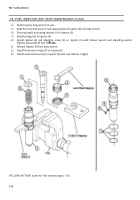
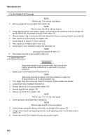
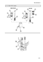
Remove screen retainer (1) and screen (2) from injector inlet port (3). Discard retaining ring (1) and
screen (2).
NOTE
Perform step 2 for non-top stop injector.
Remove plunger (5) and plunger spring (6) from injector (4).
NOTE
Perform steps 3 and 4 for top stop injector.
Using adjusting wrench and locknut wrench, remove locknut (7) and adjusting screw (8) from
injector (4).
Remove plunger (5), spring retainer (9), and plunger spring (6) from injector (4).
Place plunger (5) in injector (4).
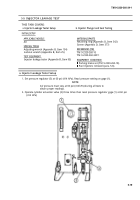
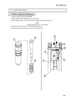
Lubricate inside of burnishing tool adapter (10) with diesel fuel.
Position injector (4) in burnishing tool adapter (10) so injector inlet port (3) and adapter inlet
holes (11) aline.
Install locating screw (12) in burnishing tool adapter (10).
Connect pressure line adapter (13) to burnishing tool adapter (10).
5-28
Back to Top

