TM-9-2320-260-34-1 - Page 80 of 657
TM
9-2320-260-34-1
3-11. EXHAUST MANIFOLD REPLACEMENT
THIS TASK COVERS:
a. Removal
b. Installation
INITIAL SETUP
APPLICABLE MODELS
All
TOOLS
General mechanic’s tool kit
(Appendix B, Item 1)
Torque wrench, 1/2-in. dr.
(Appendix B, Item 3)
MATERIALS/PARTS
Six gaskets (Appendix D, Item 113)
Gasket (Appendix D, Item 154)
Eleven locking plates (Appendix D, Item 164)
REFERENCES (TM)
TM 9-2320-260-10
TM 9-2320-260-20
TM 9-2320-260-34P-1
EQUIPMENT CONDITION
Surge tank removed (TM 9-2320-260-20).
Oil dipstick tube removed (TM 9-2320-260-20).
GENERAL SAFETY INSTRUCTIONS
Do not touch hot exhaust system components with
bare hands.
WARNING
Do not touch hot exhaust system components with bare hands.
Injury to personnel may result.
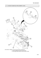
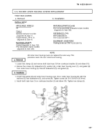
1. Remove twelve screws (1), eleven locking plates (2), and six clamps (3) from exhaust manifold (5).
Discard locking plates (2).
2. Remove four screws (11) and nuts (9) from exhaust manifold (5) and muffler exhaust flange (8).
3. Remove exhaust manifold (5) and six gaskets (4) from dowels (7) and engine (6). Discard gaskets (4).
4. Remove exhaust manifold (5) and exhaust flange gasket (10) from muffler exhaust flange (8).
Discard exhaust flange gasket (10).
5. Remove left manifold (12) and right manifold (14) from center manifold (13).
1. Install left manifold (12) and right manifold (14) on center manifold (13).
2. Position new exhaust flange gasket (10) on muffler exhaust flange (8).
3. Position six new gaskets (4) on dowels (7) and engine (6).
4. Position exhaust manifold (5) on muffler exhaust flange (8) and on dowels (7) and engine (6).
5. Install six clamps (3), eleven locking plates (2), and twelve screws (1) on exhaust manifold (5).
Tighten screws (1) to 20-25 ft-lb (27-34 N•m).
6. Install four screws (11) and nuts (9) on exhaust manifold (5) and muffler exhaust flange (8).
3-28
Back to Top


