TM-9-2320-260-34-2 - Page 227 of 863
15-44. CEILING FILLER AND SIDE PANELS REPLACEMENT
THIS TASK COVERS:
a. Left Side Panel and Filler Removal
c. Right Side Panel and Filler Installation
b. Right Side Panel and Filler Removal
d. Left Side Panel and Filler Installation
INITIAL SETUP
APPLICABLE MODELS
EQUIPMENT CONDITION
M820, M820A2
TOOLS
General mechanic’s tool kit
(Appendix B, Item 1)
MATERIALS/PARTS
Fibrous glass felt insulation
(Appendix C, Item 16)
PERSONNEL REQUIRED
•
Two
•
REFERENCES
TM 9-2320-260-10
TM 9-2320-260-20
TM 9-2320-260-34P-2
Van body sides fully expanded and secured
(TM 9-2320-260-10).
Fluorescent light fixtures removed (para. 15-92).
Blackout and emergency light fixtures removed
(para. 15-91).
Blackout switch removed (TM 9-2320-260-20).
Ceiling rear cover removed (para. 15-41).
3-phase receptacles and 400 Hz receptacles
removed (TM 9-2320-260-20).
Telephone jack removed (left side)
(TM 9-2320-260-20).
Cord box removed (TM 9-2320-260-20).
Registers and deflectors removed (para. 15-38).
•
GENERAL SAFETY INSTRUCTIONS
Gloves, eyeshields, and dust mask must be worn
during ceiling filler and side panel replacement.
WARNING
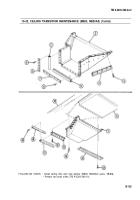
1. Remove seventy-nine screws (6) and side panel (5) from van ceiling (3), air ducts (4), and
transition (7).
2. Remove three screws (1) and filler (2) from transition (7).
b. Right Side Panel and Filler Removal
1. Remove seventy-nine screws (10) and side panel (11) from van ceiling (3), air ducts (4), and
transition (7).
2. Remove five screws (9) and filler (8) from transition (7).
NOTE
Insulate entire structure with fibrous glass felt insulation.
c. Right Side Panel and Filler Installation
1.
Install filler (8) on transition (7) with five screws (9).
2. Install side panel (11) on van ceiling (3), air ducts (4), and transition (7) with seventy-nine
screws (10).
15-166
Back to Top

