TM-9-2320-260-34-2 - Page 229 of 863
TM 9-2320-260-34-2
15-45. CEILING AIR DUCTS AND SUPPORTS REPLACEMENT
THIS TASK COVERS:
a. Removal
b. Installation
INITIAL SETUP
APPLICABLE MODELS
M820, M820A1, M82A2
TOOLS
General mechanic’s tool kit
(Appendix B, Item 1)
MATERIALS/PARTS
Primer (Appendix C, Item 31)
PERSONNEL REQUIRED
Two
REFERENCES (TM)
TM 9-2320-260-10
TM 9-2320 -260-34P-2
EQUIPMENT CONDITION
• Parking brake set (TM 9-2320-260-10).
• Van body sides fully expanded and secured
(TM 9-2320-260-10).
• Ceiling rear cover removed (para. 15-40 or 15-41).
• Ceiling filler and side panels removed
(M820, M820A2) (para. 15-44).
• Ceiling registers and deflectors removed (M820A1)
(para. 15-38).
• Ceiling lights removed (M820A1) (para. 15-93).
GENERAL SAFETY INSTRUCTIONS
Gloves, eyeshields, and dust mask must be worn
during duct and support replacement.
Van body is insulated with fibrous glass felt insulation. Gloves,
eyeshields, and dust mask must be worn during duct and support
replacement. Failure to do so may result in injury to personnel.
NOTE
• Perform step 1 for M820 and M820A2 vehicles.
• Perform step 2 for M820A1 vehicles.
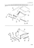
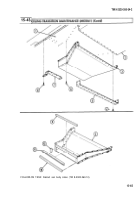
1. Remove fifty-two screws (8) and two enclosures (9) from air ducts (4) and (7).
2. Remove seventy-two screws (8) and two enclosures (9) from air ducts (4) and (7).
3. Remove fourteen screws (6) from air ducts (4) and (7) and support (3).
4. Remove sixteen screws (5) and air duct (4) from ceiling (1).
5. Remove eighteen screws (10) and air duct (7) from ceiling (1).
6. Remove nine screws (2) and support (3) from ceiling (1).
NOTE
• Perform step 7 for M820 and M820A2 vehicles.
• Perform step 8 for M820A1 vehicles.
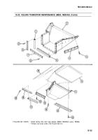
7. Remove fifty-two screws (21) and two enclosures (20) from air ducts (11) and (18).
8. Remove seventy-two screws (21) and two enclosures (20) from air ducts (11) and (18).
9. Remove eight screws (17) and four screws (19) from air ducts (11) and (18) and supports (12)
and (14).
10. Remove eighteen screws (16) and air duct (18) from ceiling (1).
15-168
Back to Top


