TM-9-2320-260-34-2 - Page 343 of 863
15-77. FLEXIBLE CONVERTER WIRING HARNESS REPLACEMENT
THIS TASK COVERS:
a. Removal
b. Installation
INITIAL SETUP
APPLICABLE MODELS
M820, M820A2
TEST EQUIPMENT
Multimeter (Appendix B, Item 115)
TOOLS
General mechanic’s tool kit
(Appendix B, Item 1)
Tool kit, electrical (Appendix B, Item 106)
REFERENCES (TM]
TM 9-2320-260-10
TM 9-2320-260-20
TM 9-2320-260-34P-2
EQUIPMENT CONDITION
(TM 9-2320-260-10).
•
Battery ground cable disconnected
(TM 9-2320-260-20).
CAUTION
Use care when replacing wiring harness. Excessive snagging or
pulling may damage wiring harness.
a. Removal
NOTE
•
The flexible converter wiring harness and 400 Hz output wiring
harness are replaced the same. This procedure covers the flex-
ible converter wiring harness.
•
Tag wires, cables, and leads for installation.
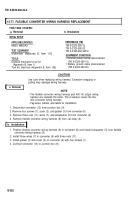
1. Disconnect connector (10) from junction box (9).
2. Remove four screws (1), cover (2), and gasket (3) from converter (6).
3. Remove three nuts (11), wires (7), and lockwasher (5) from converter (6).
4. Remove flexible converter wiring harness (8) from van body (4).
b. Installation
1. Position flexible converter wiring harness (8) in converter (6) and install lockwasher (5) over flexible
converter wiring harness (8).
2. Install three wires (7) in converter (6) with three nuts (11).
3. Install gasket (3) and cover (2) on converter (6) with four screws (1).
4. Connect connector (10) to junction box (9).
15-282
TM 9-2320-260-34-2
•
External power source disconnected
Back to Top


