TM-9-2320-260-34-2 - Page 401 of 863
16-2. FRONT WINCH REPAIR
(Contd)
APPLICABLE
MODELS
All
TOOLS
General mechanic’s tool kit
(Appendix B, Item 1)
Mechancal
puller kit (Appendix B, Item 14)
Spring tester (Appendix B, Item 10)
Torque wrench, 1/2-in. dr.
(Appendix B, Item 3)
Outside micrometer (Appendix B, Item 8)
Inside micrometer (Appendix B, Item 9)
Dial indicator (Appendix B, Item 11)
Arbor press (Appendix B, Item 7)
Soft-head hammer (Appendix B, Item 47)
MATERIALS/PARTS
Nine lockwashers (Appendix D, Item 223)
Two seals (Appendix D, Item 427)
Seal (Appendix D, Item 429)
Seal (Appendix D, Item 423)
Seal (Appendix D, Item 425)
Two gaskets (Appendix D, Item 137)
Gasket (Appendix D, Item 96)
Gasket (Appendix D, Item 97)
TWO
woodruff keys (Appendix D, Item 545)
Two woodruff keys (Appendix D, Item 556)
Two woodruff keys (Appendix D, Item 555)
MATERIALS/PARTS (Contd)
Woodruff key (Appendix D, Item 554)
Six screw-assembled lockwashers
(Appendix D, Item 383)
Expansion plug (Appendix D, Item 330)
Plug (Appendix D, Item 327)
Four lockwashers (Appendix D, Item 219)
Six lockwashers (Appendix D, Item 218)
Gear oil (Appendix C, Item 22)
Sealing compound (Appendix C, Item 45)
GAA grease (Appendix C, Item 14)
REFERENCES (TM)
LO 9-2320-260-12
TM 9-214
TM 9-2320-260-20
TM 9-2320-260-34P-2
EQUIPMENT CONDITION
●
Winch gear oil drained (LO 9-2320-260-12).
●
Winch removed (TM 9-2320-260-20).
●
Winch level wind removed (if equipped)
(para. 16-3).
Winch roller removed (para. 16-5).
GENERAL SAFETY INSTRUCTIONS
Stabilize winch while sitting vertical.
a Winch Disassembly
NOTE
Perform steps 1 and 2 if front winch is not equipped with level
wind mechanism.
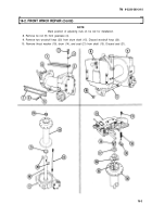
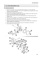
1. Remove four screws (2), lockwashers (3), and top channel (1) from gearcase (4) and end frame (8).
Discard lockwashers (3).
2. Remove four screws (6), lockwashers (5), and side channel (7) from gearcase (4) and end frame (8).
Discard lockwashers (5).
3. Remove nut (10) from tie rod (9).
NOTE
Assistant will help with step 4.
4. Turn gearcase (4) to the ground so drum (14) is vertical.
WARNING
Stabilize winch while sitting vertical. Failure to do so may result
in injury to personnel.
5. Remove end frame (8) from drum shaft (15).
6. Remove setscrew (11), drag brake (13), and spring (12) from end frame (8).
7. Remove clutch (16), thrust ring (17), and sleeve (18) from end frame (8).
16-2
TM 9-2320-260-34-2
Back to Top

