TM-9-2320-260-34-2 - Page 503 of 863
TM 9-2320-260-34-2
16-18. BOOM ASSEMBLY REPLACEMENT (M816)
THIS TASK COVERS:
a. Removal
b. Installation
INITIALSETUP
APPLICABLE MODELS
M816
TOOLS
General mechanic’s tool kit
(Appendix B, Item 1)
3/4-in. torque wrench (Appendix B, Item 2)
1-5/8-in. socket, 3/4-in. dr.
(Appendix B, Item 102)
1-718-in. socket, 3/4-in. dr.
(Appendix B, Item 135)
Torque multiplier
Blocking
Two chains
Lifting device
Guide lines
MATERIALS/PARTS
Two lockwashers (Appendix D. Item 223)
Locknut (Appendix D, Item 202)
GM grease (Appendix C, Item 14)
Antiseize tape (Appendix C, Item 50)
Cap and plug set (Appendix C, Item 6)
PERSONNEL REQUIRED
Two
REFERENCES (TM)
LO 9-2320-260-12
TM 9-2320-260-10
TM 9-2320-260-20
TM 9-2320-260-34P-2
EQUIPMENT CONDITION
●
Hydraulic reservoir drained (LO 9-2320-260-12).
●
Hoist winch cable removed (TM 9-2320-260-20).
Operator guard removed (TM 9-2320-260-20).
●
Pioneer tool bracket removed (TM 9-2320-260-20).
●
Floodlight housing and mount removed
(TM 9-2320-260-20).
GENERAL SAFETY INSTRUCTIONS
●
All
personnel must stand clear during lifting
operations.
●
Keep hands clear during removal and installation
of boom.
●
Ensure lifting capacity is greater than weight of
boom assembly.
a. Removal
●
●
WARNING
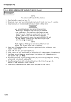
All personnel must stand clear during lifting operations.
A swinging or shifting load may cause injury to personnel.
Ensure lifting capacity is greater than weight of boom assembly.
Failure to do so may result in injury to personnel or damage to
equipment.
NOTE
Two assistants will help with this procedure.
1. Install chain on boom (1) and attach to lifting device.
2. Wrap second chain around lower boom roller (4) and inner boom (3) to hold inner boom (3)
in position.
3. Raise boom (1) to remove weight from shipper braces (2).
4. Remove two safety pins (5) and shipper braces (2) from boom (1).
5. Remove two safety pins (6), pins (8), and shipper braces (2) from brackets (7).
16-104
Back to Top


