TM-9-2320-260-34-2 - Page 67 of 863
15-3. CARGO BODY FRAME RAIL SILL REPLACEMENT
THIS TASK COVERS:
a. Removal
b. Installation
lNITIAL SETUP
APPLICABLE MODELS
M813, M813A1, M814
TOOLS
General mechanic’s tool kit
(Appendix B, Item 1)
Torque wrench, 3/8-in. dr.
(Appendix B, Item 4)
MATERIALS/PARTS
Five Lockwashers (M813, M813A1)
(Appendix D, Item 215)
Ten lockwashers (M814) (Appendix D, Item 215)
Ten locknuts (M814) (Appendix D, Item 176)
REFERENCES (TM)
TM 9-2320-260-34P-1
EQUIPMENT CONDITION
Cargo body removed (para. 15-2).
●
Left and right frame rail sills are replaced the same. This proce-
dure covers the left frame rail sill.
●
Perform steps 1 and 2 for M813 and M813A1 vehicles.
●
Perform steps 3 and 4 for M814 vehicles.
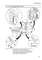
1. Remove five nuts (7), lockwashers (9), and sill (3) from cargo body (1). Discard lockwashers (9).
2. Remove five screws (8) from sill (3).
3. Remove ten locknuts (2), washers (6), lockwashers (5), and two sills (3) from cargo body (1). Discard
lockwashers (5) and locknuts (2).
4. Remove ten screws (4) from sills (3).
b. Installation
NOTE
●
Perform steps 1 and 2 for M813 and M813A1 vehicles.
●
Perform steps 3 and 4 for M814 vehicles.
1. Position sill (3) on cargo body (1) with five screws (8).
2. Install sill (3) on cargo body (1) with five new lockwashers (9) and nuts (7). Tighten nuts (7)
100-110 lb-in. (11.3-12.4 N.m).
3. Position sill (3) on cargo body (1) with ten screws (4).
4. Install sills (3) on cargo body (1) with ten new lockwashers (5), washers (6), and new locknuts (2).
Tighten locknuts (2) 100-110 lb-in. (11.3 -12.4 N.m).
15-6
TM 9-2320-260-34-2
Back to Top


