TM-9-2320-260-34-2 - Page 741 of 863
TM 9-2320-26044-2
17-16. PERSONNEL HEATER FUEL CONTROL VALVE MAINTENANCE
THIS TASK COVERS:
a. Removal
c. Installation
b. Inspection
INITIAL SETUP
Applicable MODELS
All
TEST EQUIPMENT
Multimetir (Appendix B, Item 115)
TOOLS
General mechanic’s tool kit
(Appendix B, Item 1)
Tool kit, electrical (Appendix B, Item 106)
MATERIALS/PARTS
Four screw-assembled lockwashers
(Appendix D, Item 405)
MATERIALS/PARTS (Contd)
Screw-assembled lockwasher (Appendix D, Item 402)
Two nut-assembled lockwashers
(Appendix D, Item 262)
Nut-assembled lockwasher (Appendix D, Item 263)
Antiseize tape (Appendix C, Item 50)
REFERENCES (TM)
TM 9-2320-260-20
TM 9-2320-260-34P-2
EQUIPMENT CONDITION
Personnel heater removed (TM 9-2320-260-20).
a. Removal
1.
2.
3.
4.
5.
6.
7.
8.
●
Perform this procedure for early model heaters.
• Tag all wires for installation.
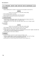
Release two dzus fasteners (10) and remove guard (1) from heater housing (6).
Remove nut-assembled lockwasher (9), screw (7), and clamp (8) from ignition control unit (2).
Discard nut-assembled lockwasher (9).
Remove screw-assembled lockwasher (3) and lead (4) from receptacle (5). Discard screw-assembled
lockwasher (3).
Remove nut-assembled lockwasher (13) and three leads (11) from overheat switch (12). Discard
nut-assembled lockwasher ( 13).
Remove nut-assembled lockwasher (14) and lead (15) from overheat switch (12). Discard nut-
assembled lockwasher (14).
Disconnect fuel outlet line (20) from fuel control valve (16).
Remove four screw-assembled lockwashers (19) and fuel control valve (16) from heater housing (6).
Discard screw-assembled lockwashers (19).
Remove elbow (18) and nipple (17) from fuel control valve (16).
Inspect fuel control valve (16) for grooves, dents, and loose or damaged wiring. Replace fuel control
valve (16) if grooved, dented, or wiring is loose or damaged.
17-40
Back to Top


