TM-9-2320-272-23-2 - Page 1085 of 1417
ADJUSTMENT
WARNING
Do not disconnect air lines or hoses before draining air reservoirs. Small parts under pressure
may shoot out with high velocity. Failure to comply may result in injury or death to personnel.
1.
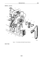
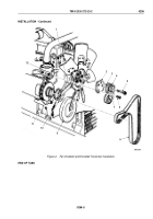
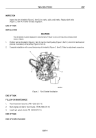
Disconnect air line (Figure 1, Item 13) from elbow (Figure 1, Item 10).
2.
Remove elbow (Figure 1, Item 10) and adapter (Figure 1, Item 12) from union (Figure 1, Item 11).
3.
Loosen three screws (Figure 1, Item 1) on fan pulley bracket (Figure 1, Item 6).
4.
Loosen jamnut (Figure 1, Item 2) on adjusting screw (Figure 1, Item 3) on water pump clamp ring
(Figure
1,
Item 4).
5.
Using belt tension gauge (Figure 1, Item 7) on inner belt midway between pulleys, adjust tension of inner belt
(Figure 1, Item 5) by turning screw (Figure 1, Item 3). Tension should be 95 to 105 lb-ft (423 to 467 N·m) for
a new belt and 85 to 95 lb-ft (378 to 422 N·m) for a used belt.
6.
Repeat tension check of Step (5) for outer belt (Figure 1, Item 5). Recheck inner belt.
NOTE
Belts must be replaced as a matched set.
7.
If either inner or outer belts (Figure 1, Item 5) cannot be adjusted in proper range, replace both belts.
8.
Tighten top screw (Figure 1, Item 1) 25 to 35 lb-ft (34 to 47 N·m). Tighten two side screws 25 to 35 lb-ft
(34 to 47 N·m).
NOTE
Male pipe threads must be wrapped with antiseize tape before installation.
9.
Install adapter (Figure 1, Item 12) and elbow (Figure 1, Item 10) on union (Figure 1, Item 11).
10.
Connect air line (Figure 1, Item 13) to elbow (Figure 1, Item 10).
TM 9-2320-272-23-2
0297
0297-2
Back to Top

