TM-9-2320-272-23-2 - Page 1237 of 1417
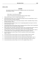
REMOVAL
NOTE
•
When removing CTIS wiring harness, note location of all tiedown straps and protective
covering for installation.
•
Tag all wiring harness leads and note routing for installation.
1.
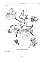
Disconnect wiring harness connector (Figure 1, Item 12) from electronic control unit (ECU) receptacle
(Figure
1, Item 11).
2.
Disconnect wiring harness connector (Figure 1, Item 9) from amber warning light wire (Figure 1, Item 10).
3.
Disconnect wiring harness connector (Figure 1, Item 18) from power and ground cable (Figure 1, Item 17).
4.
Disconnect wiring harness connector (Figure 1, Item 15) from blackout wire (Figure 1, Item 16).
5.
Disconnect wiring harness connector (Figure 1, Item 20) from pressure transducer (Figure 1, Item 19).
6.
Disconnect wiring harness connector (Figure 1, Item 22) from pneumatic controller solenoid receptacle
(Figure
1, Item 21).
7.
Disconnect wiring harness connector (Figure 1, Item 1) from speed signal generator wire (Figure 1, Item 23)
on transfer case (Figure 1, Item 5).
8.
Disconnect wire (Figure 1, Item 4) from pressure switch wire (Figure 1, Item 24) located on right frame rail
(Figure 1, Item 2) above wet tank (Figure 1, Item 3).
9.
Remove screw (Figure 1, Item 26), washer (Figure 1, Item 27), and clamp (Figure 1, Item 28) from wiring
harness (Figure 1, Item 7) and bracket (Figure 1, Item 25).
10.
Remove screw (Figure 1, Item 30), washer (Figure 1, Item 29), and clamp (Figure 1, Item 31) from wiring
harness (Figure 1, Item 7) and firewall (Figure 1, Item 13).
11.
Remove wiring harness (Figure 1, Item 7) from frame rails (Figure 1, Items 2 and 8) and crossmember
(Figure
1,
Item
6).
12.
Carefully pull wiring harness (Figure 1, Item 7) through grommet (Figure 1, Item 14) on firewall
(Figure
1,
Item
13).
NOTE
Perform Step (13) if grommet is damaged.
13.
Remove grommet (Figure 1, Item 14) from firewall (Figure 1, Item 13). Discard grommet.
TM 9-2320-272-23-2
0322
0322-2
Back to Top


