TM-9-2320-272-23-2 - Page 1230 of 1417
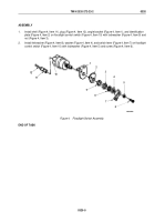
ASSEMBLY
1.
Install shell (Figure 4, Item 11), plug (Figure 4, Item 12), angle bracket (Figure 4, Item 1), and identification
plate (Figure 4, Item 2) on floodlight control switch (Figure 4, Item 10) with lockwasher (Figure 4, Item 9) and
nut (Figure 4, Item 3).
2.
Install felt washer (Figure 4, Item 8), washer (Figure 4, Item 4), and switch lever (Figure 4, Item 7) on floodlight
control switch (Figure 4, Item 10) with lockwasher (Figure 4, Item 5) and screw (Figure 4, Item 6).
M9503DAA
12
11
10
9
8
7
6
1
2
3
4
5
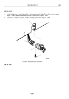
Figure 4.
Floodlight Switch Assembly.
END OF TASK
TM 9-2320-272-23-2
0320
0320-5
Back to Top


